Translated from an article published in DTM Magazine (Japan) Vol.112.
The article was written by HIRASAWA Eiji.
- What is VOID Modular System?
- Installation and setting up a synthesizer.
- Analog synthesizer configuration + functions of the parameters.
What is VOID Modular System?
VOID Modular System is a software sound source for Windows which comes in the form of a VST2.0-compatible plug-in.
Being a modular analog synthesizer simulator, its main characteristic is that it emulates the process of configuring a synthesizer
by allowing you to combine modules to put together your own synthesizer. On the one hand, with its high level of freedom, it makes it possible to enjoy building a wide variety of sounds, but on the other hand, its weakness is that beginners have no idea
about what they should do and how they should proceed.
To address this point, I shall introduce the roles of various modules, as well as how to connect them, by assembling a basic minimalistic synthesizer system. Also, since I shall introduce the
basics of sound creation, I hope that even people who never used a synthesizer before will take up the challenge.
[ … ]
Installation and setting up a synthesizer.
Installing VOID is quite easy … you simply need to proceed according to the installer's messages. Basically, you should be able to proceed without any problem by simply clicking "Yes", "OK" and "Next" [1].
After
installing VOID successfully, it can be used by loading it into the VST instrument host application just as you would do for any other sound source plug-in [2].
[1]
During the installation, you will be asked to specify the installation location for VSTi plug-ins. We recommend that you select the location where other VSTi already used by your host application are installed.
[2]
… VOID will be displayed in the VST instrument list. After assigning it, pressing the EDIT button will open VOID's screen; at that point, press OK on the splash screen to close it. Note that no sound will come out unless VOID is selected as the MIDI output port on the track side.
#Preparing initialized patch data.
[3] Patch memory selection / Patch data initialization.
Patch memory is organized in 10 banks (bank0 - bank9) able to store 128 patches each. Since bank0 contains preset patches, let's change the bank and choose one that is empty. If you wish to discard previous patch data, click the INIT button in the PRESET area. All modules except for the I/O module will be deleted and you will be able to build sounds from scratch.
#Basic operations for building a synthesizer.
[4] Adding / Deleting modules.
Click the MODULES area and select from the list the module you wish to add. The module will be added to the rack area and you can then move it to the desired location by simply dragging it with the mouse. To delete a module, right click on the module and select DELETE from the pop-up menu.
[5] Connecting modules using patch cables.
Dragging the mouse between the terminals on modules will make cables appear to connect those terminals. You can connect a single OUT terminal to multiple IN terminals, but connecting IN terminals together or OUT terminals together, as well as connecting together terminals that handle different types of signals is not allowed. To remove a connection, simply click on the terminal on the IN side.
Analog synthesizer configuration + functions of the parameters.
Let's now proceed with adding the basic modules of a synthesizer while introducing the modules' functions.
#The I/O module: Input / Output of audio and control signals.
The I/O module, which remains even after doing an initialization, is used for the input and output of the control and audio signals involved in a musical performance. Its upper part contains the terminals for the control signals that are sent to all kinds of modules, while its lower part contains the terminals for outputting the audio signals coming from the modules to the outside world.
[6] I/O Module
CV (Control Voltage terminal): Outputs the pitch signal.
GATE (Gate terminal): Outputs the note on/off signal (note on = maximum value, note off = 0).
AUDIO (Audio terminal): Outputs the sounds created by VOID to the host application.
#OSC module (Oscillator): Transmission of the waveforms at the origin of sounds.
In analog synthesizers, the waveforms that form the root of sound generation are output by a transmitter called an oscillator. As the first step, by adding and connecting an OSC module, we will be able to play some sounds by clicking on the keyboard at the bottom of the window.
[7] Add an oscillator to the rack.
Choose "Oscillator" from the module list and place it next to the I/O module.
[8] Connect the patch cables.
Connect together the CV terminals on the I/O and OSC modules, the GATE terminal on the I/O module to the AMP terminal on the OSC module and the WAVE terminal on the OSC module to the AUDIO terminal on the I/O module, as shown on the figure.
[9] OSC Module.
AMP: Input for the signal governing the pitch.
WAVE: Output for the oscillator's waveform (audio signal).
TYPE: Selects the oscillator's waveform (Sin, Saw, Pulse, Noise).
OCT: Specifies an octave range.
NOTE: Shifts the pitch by half tone increments.
FINE: Shifts the pitch by fine increments.
#ADSR Envelope Module: Temporal modification of sounds.
In the current state, we can only emit simple sounds where the volume is maximal when the note is ON and the volume is 0 when the note is OFF. We shall now add a new module allowing us to configure volume variations according to time. The ADSR Envelope module is able to create control signals to implement gradual modifications according to time. By sending the signal from the ADSR Envelope module to the AMP terminal which controls the volume on the OSC module, we can create volume variations.
[10] Add an ADSR Envelope module to the rack.
Choose "ADSR Envelope" from the module list and place it next to the OSC module.
[11] Connect the patch cables.
As shown on the figure, disconnect the GATE terminal on the I/O module from the AMP terminal on the OSC module and connect it to the IN terminal at the top of the ADSR module. Also, connect the OUT terminal on the ADSR module to the AMP terminal on the OSC module.
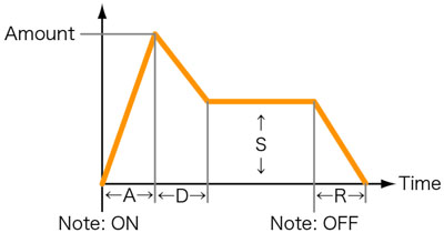
The envelope module allows us to adjust four parameters. The attack time (A) defines the time required to reach the maximal value after Note On is activated. The sustain level (S) defines the value that is sustained until Note Off. The decay time (D) defines the decay time it takes for the value to go from its maximum level to its sustain level. Finally, the release time (R) defines the time it takes for the value to become 0 after Note Off. By adjusting these parameters, we can build a waveform that changes the level according to time (envelope curve) [12].
[12] Envelope Curve.
[13] ADSR Envelope Module.
IN: Input for the signal that acts as the trigger activating the envelope.
OUT: Outputs the waveform created by the envelope.
A: Attack time (defines the rise time).
D: Decay time (defines the decay time).
S: Sustain level (defines the level that is sustained).
R: Release time (defines the duration of the trailing note).
AMOUNT: Defines the maximal value of the envelope curve.
#Filter module: Modification of the overtone of the audio signal.
As it is now, we can only obtain the timbre corresponding to the waveform defined by the oscillator's configuration. We shall now add a module allowing us to modify the timbre by manipulating that waveform. The filter module allows us to define a frequency band and only let through the frequencies of the input audio signal that fit within that band. We can therefore take the output of the oscillator and create timbre changes that modify its waveform overtones.
[14] Add a Filter module to the rack.
Choose "Filter LP/HP/BP/Notch" from the module list and place it next to the ADSR Envelope module.
[15] Connect the patch cables.
As shown on the figure, disconnect the WAVE terminal on the OSC module from the AUDIO terminal on the I/O module and connect it to the IN terminal at the top of the Filter module. Also, connect the OUT terminal on the Filter module to the AUDIO terminal on the I/O module.
[16] Filter Module
IN: Audio signal input to the filter.
OUT: Filtered output audio signal.
TYPE: Filter type selection.
・LP: Low-pass. Lets through frequencies lower than the cutoff frequency.
・HP: High-pass. Lets through frequencies higher than the cutoff frequency.
・BP: Band-pass. Lets through frequencies centered around the cutoff frequency.
・BR: Notch. Blocks frequencies centered around the cutoff frequency.
RESO: Resonance. Adds a peculiarity to the timbre by emphasizing the band close to the cutoff frequency.
LP (low-pass) filters are usually used to create sounds. By rotating the CUTOFF knob from right to left, the sound becomes rounder (softer). Also, by using a low cutoff frequency and rotating the RESO knob to the right, we can give a peculiarity to the sound that is a little like someone pinching their nose.
HIRASAWA Eiji: Composer, music magazine contributor, technical school teacher, involved in all kinds of musical endeavors, "musical jack of all trades".
DTM Magazine (Japan)
Published by TERAJIMA JOHO KIKAKU Co., Ltd.
http://www.dtmm.co.jp/