Translated from an article published in DTM Magazine (Japan) Vol.112.
The article was written by HIRASAWA Eiji.
- Let's add temporal changes to the timbre too.
- Let's add thickness to the sound.
- Let's try building an effects unit.
- The possibility of free sound creation.
Let's add temporal changes to the timbre too.
[17] Add an ADSR Envelope module to the rack.
Choose "ADSR Envelope" from the module list and place it next to the Filter module.
[18] Connect the patch cables.
Connect the GATE terminal on the I/O module to the upper IN terminal on the ADSR2 module and the OUT terminal on the ADSR2 module to the IN terminal next to the CUTOFF knob on the Filter module. The effect is that the cutoff frequency that was previously adjusted with the knob will now be given a shape defined by the output of the envelope [19].
[19]
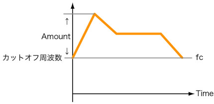
In the case of a low-pass filter, the timbre will become brighter for a duration defined by the attack time, it will become softer until the value defined by the sustained level in a time defined by the decay time, and at Note off, it will return to the value defined by CUTOFF in a time defined by the release time. The breadth of the timbre changes can be adjusted with the AMOUNT knob.
#LFO module: Cyclic modifications of sounds.
Next, let's add an element indispensable to an expressive musical performance: vibrato. The LFO is a module that outputs a control signal which cyclically rises and falls. Since vibrato is a musical effect consisting of a pulsating change of pitch, it can be obtained by pulsating the pitch of the OSC module using the output of the LFO module.
[20] Add a LFO module to the rack.
Choose "LFO" from the module list and place it under the I/O module.
[21] Connect the patch cables.
Connect the OUT terminal on the LFO module to the FM terminal on the OSC module.
Tip
On the OSC module, the CV terminal acts as the input for the pitch information. The FM (frequency modulation) terminal acts as the input for information used to modify that pitch.
[22] LFO Module.
OUT: Outputs the LFO signal.
TYPE: LFO output waveform selection (sin, pulse, random).
FC: Frequency. Adjusts the pulsation speed of the LFO.
AMT: Amount. Adjusts the amplitude of the modulation.
[23]
Increasing the value of Amount causes the vibrato effect to be applied constantly. However, by turning the modulation wheel at the left of the keyboard on the bottom of the screen while Amount is 0, a vibrato effect with an arbitrary amplitude can be applied.
Let's add thickness to the sound.
Until now, we only lined-up modules in one series to create our sounds. By adding even more modules, we can obtain more complex and thicker sounds.
#Add a second oscillator.
By adding oscillators, we can of course combine different waveforms, but we can also overlay sounds with different pitches to obtain octave unison or create out of tune effects by adding the same sound with a slightly shifted pitch, thus adding gloss and thickness to our sounds. These can be adjusted using the 3 knobs at the bottom of the OSC module (OCD, NOTE and FINE).
[24] Add an oscillator and a mixer to the rack.
Choose "Oscillator" from the module list and place it to the right of the LFO module. Choose "Mixer 4in 1out" from the module list and place it to the right of the OSC2 module.
[25] Connect the patch cables.
Connect together the CV terminals on the I/O and OSC2 modules as well as the OUT terminal on the ADSR module to the AMP terminal on the OSC2 module. Also, connect the OUT terminal on the LFO module to the FM terminal on the OSC2 module (see the ○ marks).
*The wiring display mode was switched to random to make the wiring more visible.
[26]
Disconnect the WAVE terminal on the OSC module from the IN terminal on the Filter module and connect it to the IN terminal of channel 1 on the Mixer module. Connect the WAVE terminal on the OSC2 module to the IN terminal of channel 2 on the Mixer module. Finally, connect the OUT terminal on the Mixer module to the IN terminal on the Filter module (see the ○ marks).
Since there are now 2 series of oscillators, we built a patch that sends the mixed signal produced by the mixer module to the filter.
[27] Mixer Module.
IN1 - 4: Input terminals for each channel.
OUT: Output terminal.
VOL: Regulates the volume for each channel.
PAN: Defines the position for each channel.
[28]
Example of the settings for 2OSC-1Filter-2EG-1LFO×2 series.
In the example below, effects are also setup.
Tips
By having 2 series of not only the oscillators but also the filters and all other modules, and by having a mixer mixing the signals right before sending them to the AUDIO terminal on the I/O module, 2 completely different timbres can be built and superimposed.
Let's try building an effects unit.
We add even more modules to get richer sounds.
#Try using delays.
[29] Add an effects unit to the rack.
Choose "Delay" from the module list and place it to the right of the Mixer module.
[30] Connect the patch cables.
Disconnect the OUT terminal on the Filter module from the AUDIO terminal on the I/O module and connect it to the IN terminal on the Delay module. Connect the OUT terminal on the Delay module to the AUDIO terminal on the I/O module.
[31] Delay Module
IN: Input terminal.
OUT: Output terminal.
TIME: Adjusts the delay time.
FEEDBACK: Adjusts the quantity of feedback.
DRY/WET: Adjusts the balance between the raw sound and the effect's sound.
[32]
When using other effects, you should connect them in series between the OUT terminal on the Filter module and the AUDIO terminal on the I/O module. You can also use effects in parallel by forking the output of the filter to multiple effect modules whose outputs are mixed using a Mixer module and then sent to the AUDIO terminal on the I/O module.
The possibility of free sound creation.
This time, I introduced how to connect basic modules, but the characteristic of a modular synthesizer is that it allows you to connect all kinds of modules in any way you like. For example, it is possible to insert an effect right after the oscillator and send the output to the filter, or to vary the parameters of an effect using an envelope. Also, since this is a software sound source, we can't overlook the possibility of adding as many modules as allowed by the computer's processing power. I wish that you will all use VOID to explore the possibilities of modular synthesizers.
HIRASAWA Eiji: Composer, music magazine contributor, technical school teacher, involved in all kinds of musical endeavors, "musical jack of all trades".
DTM Magazine (Japan)
Published by TERAJIMA JOHO KIKAKU Co., Ltd.
http://www.dtmm.co.jp/